
Line load
kg/m = loaded product mass / loaded length
Use the actual distribution and include concentrated loads rather than assuming an even spread.
Engineering calculations
Use transparent first-principle checks for speed, pitch, incline, load, accumulation and drive duty before the final component design is approved.
Transparent first checks
These calculations are pre-design checks, not a substitute for component selection, a risk assessment or validation by the conveyor manufacturer. Use actual product data and supplier limits for the selected belt, chain, roller, motor, gearbox and controls.
Load and drive framework
For a steady conveyor, mechanical power is the total tractive force multiplied by conveyor speed. The selected motor and gearbox must also cover efficiency losses, starting, acceleration, starts per hour and the service conditions defined by the component suppliers.
kg/m = loaded product mass / loaded length
Use the actual distribution and include concentrated loads rather than assuming an even spread.
Flift = m × g × sin θ
Add belt or chain resistance, guide friction and acceleration separately.
Pmech = Ftotal × v
Motor power is greater after drive efficiency and duty factors are applied by the design engineer.
Reference basis
The three-roller planning principle is described in Interroll planning basics. Belt pull, drive arrangement and component limits require the selected belt manufacturer's engineering method; Habasit’s fabric conveyor belt engineering guide is one example of a primary engineering reference.
Continue with the speed-control guide, sizes and widths guide and transfer layout details.
FAQs
No. They provide first checks. Final motor and gearbox selection must include conveyor resistance, efficiency, acceleration, duty, starts, component limits and supplier data.
Throughput depends on how much conveyor length each product occupies, including the intended gap between products.
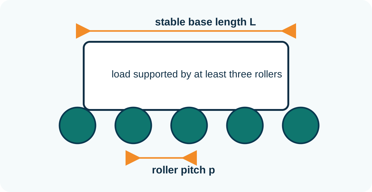
No. It is a starting geometry check based on three-roller support. Roller capacity, base stiffness, mass distribution and transfers may require closer pitch.
Use the arctangent of vertical rise divided by horizontal run. Product suitability still requires a realistic trial.
Record input values, units, assumptions, product condition, selected components and the person or source that verified the limits.
No. Speed control does not replace correct motor, gearbox and mechanical design.
Engineering enquiry
Send the product range, route, output and environment so Lancing can review the conveyor requirement under representative conditions.
Additional transparent calculations
These two calculations organise measured inputs for engineering review. They do not select a motor, gearbox, roller, shaft, bearing or belt. Final component selection must apply the selected manufacturers’ ratings, efficiencies, duty factors, starting conditions and safety requirements.
| Calculation record | Minimum information | Reason for retaining it |
|---|---|---|
| Input source | Measured value, drawing reference, sample ID or supplier document. | Allows the value to be checked when the product or component changes. |
| Units and conversions | Original units, converted units and rounding used. | Prevents silent errors between millimetres, metres, seconds and minutes. |
| Operating state | Empty, normally loaded, maximum credible load, steady run, start or fault recovery. | Shows which duty the result actually represents. |
| Assumptions | Friction, distribution, efficiency, acceleration, service factor or unverified geometry. | Identifies values that require supplier confirmation or a representative trial. |
| Acceptance link | Drawing, test step or inspection that will confirm the assumption. | Connects a calculation to a practical approval rather than leaving it as an isolated number. |
Provide the complete load range, route, lift, surface speed, acceleration expectation, starts per hour, loaded restart condition and environment. Include the effective drive diameter if converting surface speed to rotational speed. For line load, record concentrated loads as well as the average value; an even kg/m result can conceal a single heavy product or workstation load.
Use the transfer-layout guide to define geometry, and the controls, safety and washdown guide to document operating states and environment.
Calculation questions
Calculations are most useful when every input is traceable and the result is treated as part of an engineering decision rather than a catalogue selection made in isolation.
Route geometry, initial surface speed, product pitch, approximate line load, incline rise and run, and a preliminary accumulation requirement can often be calculated from controlled input data. These calculations help expose missing information and compare concepts.
They do not confirm friction, product stability, transfer behaviour, sensor detection, final component ratings or acceptance of a particular belt, chain, roller, motor or gearbox. Those items depend on selected components and representative testing.
Throughput is the number of acceptable products delivered in a period; conveyor speed is the surface travel rate. The link between them depends on product pitch, gaps, slip, stops, accumulation, reject events and process dwell. A faster conveyor can still deliver poor throughput if products arrive irregularly or the next machine controls release.
Always record the intended centre-to-centre product pitch with the target good output.
Label each input as measured, specified, assumed or derived, and record its source, unit, date and responsible person. Where a value varies, use the credible operating range and identify the condition that produces the highest demand. Do not hide uncertainty by presenting a calculated result with more precision than the inputs support.
An open assumption should become a trial, measurement or supplier-verification action before final approval.
Final verification is required when the selection depends on the actual belt, chain, roller, bearing, motor, gearbox, drive, VFD or sensor data. The supplier should be given the real duty: load distribution, resistance, incline, speed range, starts, environment, cleaning, control method and any holding or braking requirement.
A web formula can organise inputs and screen concepts, but it cannot replace the selected manufacturer data or the competent project-specific engineering review.
See how to separate preliminary evidence from final approval.
Browse the powered conveyor question library for related specification answers.